

Overview
Installation Directory Content
The CETONI SDK for Raspberry Pi archive extracts a number of files into the final SDK folder. The following overview shows which files are available in which directories:
- Root SDK Folder - contains all unit test cases.
- config - provides the configuration files for running the provided tests (the configuration use simulated devices only)
- doc - contains this HTML documentation
- examples - here you find a number of C examples that show how to use the different labbCAN libraries
- include - contains the C include files for each single labbCAN library
- lib - Contains all shared libraries of the SDK. Unlike the Linux SDK the Raspi SDK does use the system's libraries. See the Requirements and Dependencies section for more information on what libraries are required for the SDK.
- plugins - contains the LED array plugin and may be used for later addition of custom plugins
- python - Contains the complete Python integration for the CETONI SDK
- sila - The Python based SiLA library for CETONI devices
Requirements and Dependencies
- Note
- There are two versions of the SDK available: a 32- and a 64-bit version.
The 32-bit version has been compiled for and has only been tested on a Raspberry Pi 3B+ running Raspberry Pi OS Buster (version July 2019) and a Raspberry Pi Zero W running Raspberry Pi OS Buster (version August 2020). It should also work on all other Raspberry Pi models using the 32-bit RPi OS.
The 64-bit version of the SDK has been compiled for and has only been tested on a Raspberry Pi 4 running Raspberry Pi OS Bullseye (version July 2023)! It should work on all other Raspberry Pi models with the ARMv8 aarch64 architecture using the 64-bit RPi OS.
Other Raspberry Pi models and OS versions than the ones mentioned above should work as well but we cannot guarantee it!
The CETONI SDK depends on the Qt5 libraries Qt5Core and Qt5SerialPort. You need to ensure that both libraries are properly installed on your Raspberry Pi. Using the apt package manager installing the qtbase5-dev and libqt5serialport5-dev packages will give you these libraries.
Further you will need the following system libraries for the SDK to work properly:
- libsocketcan
- libboost-
- chrono
- filesystem
- locale
- serialization
- system
- thread
- timer
- test
The boost libraries need to have the same version that we used to compile the SDK. Since newer versions of RPi OS only include more recent versions of boost you need to add a source list file for apt that will allow you to install the older boost version as well.
The following command will add the file buster.list to the /etc/apt/sources.list.d/ directory:
For the 64-bit RPi OS this command has to be:
After this you need to run
to update the package lists.
Now you can easily install all libraries by running the following command on your Raspi:
Connecting the Raspi to your CETONI system
To use the Raspberry Pi for controlling all of CETONI's devices, you need to connect directly to the CAN bus. There are two possibilities how you can do this: using a CAN bus board or connecting via USB using the SYS TEC SocketCAN driver. Both options are described below.
Option 1 - Connecting via USB using the SYS TEC SocketCAN driver
- Note
- This option can only be used if you have a CETONI Base Module with the SYS TEC CAN adapter. If you have a different Base Module you need to connect your Raspberry Pi with a CAN bus board.
Hardware Setup
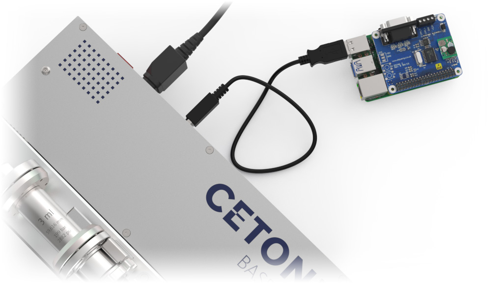
Connect the USB-A interface of your Raspi to the USB-B interface of your CETONI Base Module and power the Raspi via your Raspberry Pi USB power supply.
Installation
- Note
- There are two ways how you can install the SocketCAN driver. Both are described in the README file included with the source files of the driver. We recommend using
dkmsto install the driver as it's easier and has the advantage that the driver will automatically be rebuilt when you switch to a new kernel.
Before you continue, you need to make sure thatdkmsis installed on your system. If not you can install it with
Download the source files for the SYS TEC SocketCAN driver from their website. The version V1.0.3 has been successfully tested to work on a Raspberry Pi 4B.
Next, extract the contents of the archive you just downloaded. Then change into the extracted directory:
Now you can build and install the driver simply with
Testing
After you've successfully installed the driver and connected your CETONI Base Module via USB to your Raspberry Pi you should see a new CAN interface (usually called can0) show up:
After disconnecting and plugging in the USB cable or after each restart/hibernation the correct CAN bitrate must be set and the CAN interface needs to get started. This can be done with
You can easily test if the connection is working by using the candump tool (from the can-utils package), for example. Just start the tool and power on your CETONI Base Module. Then you should see the CAN messages on the bus:
Option 2 - Connecting with a CAN bus board
Required Hardware
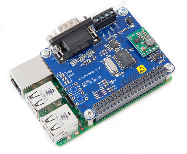
Since the Raspi does not have any CAN interfaces, you need to use a CAN bus board to connect to the bus either via DB9 or 3 way screw terminal. The following hardware components are required:

Hardware Setup
Mount the PiCAN board on your Raspberry Pi. Refer to the User Guides for PiCAN 2 or PiCAN 3 for more information and detailed instructions on the hardware installation of the board.
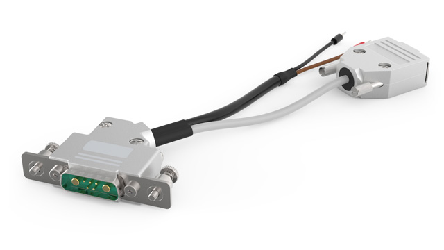
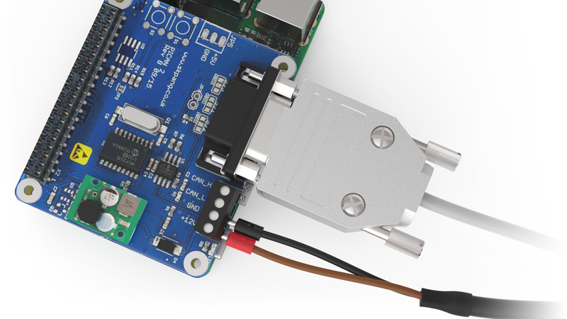
Connect the CETONI CAN-Power-Cable to the PiCAN board connectors like shown below. The PiCAN board has a 3A switching mode power supply (SMPS) with reverse polarity protection and 6V to 24V input range. This makes it possible to power the Raspberry Pi directly via the 24V of the CETONI devices. You just need to connect the ground and the 24V wires of the CETONI CAN-Power-Cable to the GND and 12V input pins of the 4 way screw terminal on your PiCAN board:
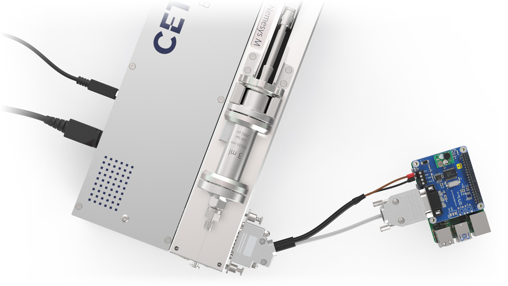
Plug in the male CETONI plug of the CAN-Power-Cable into the socket of the last module of your system where you would normally plug in the bus termination plug. The following picture shows the connection to a Nemesys M pump that is powered by a Base 120 module:
- Note
- Ensure the the CAN bus is properly terminated with two 120Ω terminators. One terminator is inside of the Base 120 module so you just need to take care of the termination of the Raspberry Pi side. You have three options:
- if you use a CETONI CAN-Power-Cable, then this cable is already properly terminated and you are done
- if you use a custom cable, then you can activate the 120Ω terminator on the PiCAN board by soldering a jumper or
- you can add an IXXAT CAN Bus Terminator to the PiCAN DP9 connector.
Using the SDK
Further information on how to use the SDK and getting started with development can be found in the CETONI SDK Linux Documentation.
If you would like to use the Raspberry Pi as a SiLA 2 server to control your CETONI devices via SiLA 2, continue with the CETONI SDK SiLA Documentation.